Image Production · X-Ray Tube
Labeled x-ray tube diagram: construction, line focus & anode heel
This labeled x-ray tube diagram is built for ARRT Image Production—not a generic anatomy atlas. Use the free preview to learn the parts of the tube and how the angled target creates both the line-focus principle and the anode heel effect. Unlock deeper interactive modes when you want to drive the model yourself.
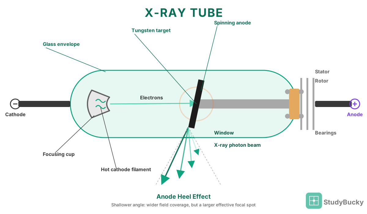
Parts of the x-ray tube (labeled)
- Cathode (filament + focusing cup). Stems name the filament as the electron source and the focusing cup as what narrows that cloud toward the target.
- Anode (rotating target / focal track). Stems name the rotating anode or tungsten target as where electrons strike and x-rays are produced.
- Evacuated glass or metal envelope. Stems name the envelope as the vacuum housing that lets electrons travel from cathode to anode.
- Tube window. Stems name the window as the thin port that lets the useful beam exit the envelope.
- Rotor/stator. Stems name the stator (outside) and rotor (inside) as the induction motor that spins the anode.
- Housing / oil. Stems name the housing and insulating oil as what absorbs unused radiation and dissipates heat.
Line-focus principle
The actual focal spot is the area electrons strike on the anode. It is kept large so heat spreads instead of melting the target.
The effective focal spot is that same area as projected toward the patient. It is kept small so recorded detail stays sharp.
Target angle makes both true at once. A smaller angle yields a smaller effective spot.
Anode heel effect
Beam intensity is higher on the cathode side of the field, because photons on the anode side travel through more target material.
Place the thick end of the part toward the cathode. Femur and AP T-spine stems are written around that rule.
Actual vs effective focal spot
The actual focal spot is the physical area of the anode that electrons strike, and it should be large so heat capacity stays high.
The effective focal spot is the area projected toward the patient and the receptor, and it should be small so edges record sharply.
Angling the target face is what lets both be true at the same time: shrinking the angle shrinks the effective spot without shrinking the actual area of electron interaction.
Geometric unsharpness is the calculation that follows from that effective size together with OID and SOD.
Frequently asked questions
What should a labeled x-ray tube diagram include for the ARRT?
Cathode (filament and focusing cup), anode/target, envelope, window, and housing—plus how target angle sets the effective focal spot (line focus) and the anode heel effect.
What is the line-focus principle?
Angling the anode lets a large actual focal spot (heat capacity) project as a smaller effective focal spot (sharper detail).
Which side of the beam is stronger in the anode heel effect?
The cathode side. Place thicker anatomy toward the cathode.
Interactive diagram
Free layer covers the labeled tube + both principles. Unlock full access to drive the interactive model and linked Image Production practice.