Image Production · Image Quality
Beam geometry in radiography: SID, OID, magnification & blur
Beam geometry is how SID, OID, and focal-spot size shape magnification and sharpness on the radiograph. This diagram shows why a part held off the receptor images larger and less sharp—and why lengthening SID buys back some of what OID costs you.
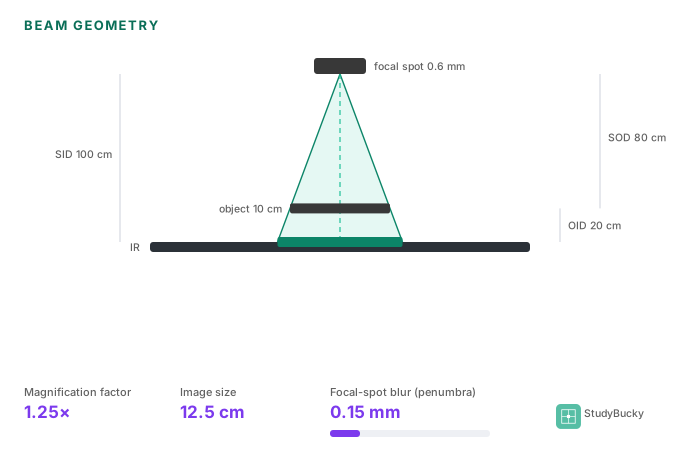
SID, OID, and SOD
- SID. Source-to-image distance — tube to receptor.
- OID. Object-to-image (part-to-receptor) distance.
- SOD. Source-to-object distance. Stems often give SID and OID and expect SOD = SID − OID.
Magnification factor
M = SID / SOD
Anything held away from the receptor casts a larger shadow (size distortion). Keep the part against the receptor when you can.
Focal-spot blur (penumbra)
Blur ≈ effective focal spot × OID / SOD
The focal spot is not a true point, so edges land as an unsharp band. Smaller effective spot, smaller OID, larger SOD → less blur.
When OID is fixed, SID is your lever
If anatomy forces OID, lengthening SID pulls M toward 1 and shrinks blur as SOD grows (why chest PA uses a long SID). Cost: receptor exposure falls with distance squared—raise mAs to compensate (inverse/direct square).
Frequently asked questions
What is the magnification factor in radiography?
M = SID / SOD. Larger OID (or shorter SID) increases magnification. SOD is often calculated as SID − OID.
How does OID affect spatial resolution?
Increasing OID increases magnification and focal-spot blur (penumbra), which decreases spatial resolution—unless you compensate with SID/focal-spot choices.
Why does a longer SID help when the part can’t touch the receptor?
It increases SOD, which lowers magnification and blur. You typically raise mAs because intensity falls with the square of distance.
Interactive diagram
Free layer covers SID/OID/SOD, magnification, and blur. Unlock full access to drive the model and linked Image Production practice.